|
|
|

|
  CUSTOMER SUPPORT CUSTOMER SUPPORT  Technical Data Technical Data  Installation Installation |
|
|
|
|
| |
 |
|
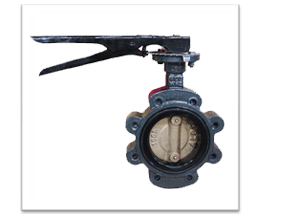
| This manual describes "Installation, Operation and Maintenance of DK-C Series butterfly valve. |
 |
|
|
 |
|
DK-C sereies is the particular term of DK TMI to distinguish from other types of valves and is nomally called as Concentric Butterfly Valve in the valve industry. DK-C series valve of which retentive elastomer liner can be replaced on site without extra tools complete, permanent and continuous leak-tightness provided by spherical contact between the disc and the liner and shaft sealing provided by flately raised seat surface and polished disc-hub area.
Also, a perfect zero leakage seal at bi-direction is obtained by the compression of the inner between the valve body and the edge of the disc. A perfect zero leakage seal is provided by means of flatted liner area around both up and down shaft passages and the spherically machined disc. |
|
 |
DK C-Series is generally classified by open/closed method as follows.
(1) By Operator(Only in Manual)
- Lever Type
This valve type can be opened or closed by operator personally
- Hand wheel operating type
This valve has the reduction gear box with hand wheel on the top of valve.
the operation shall be made as indicator by operator.
(2) By Appearance
DK-C series is Classified as Wafer type, Lug Type and Flange type acc. To it's appearance.
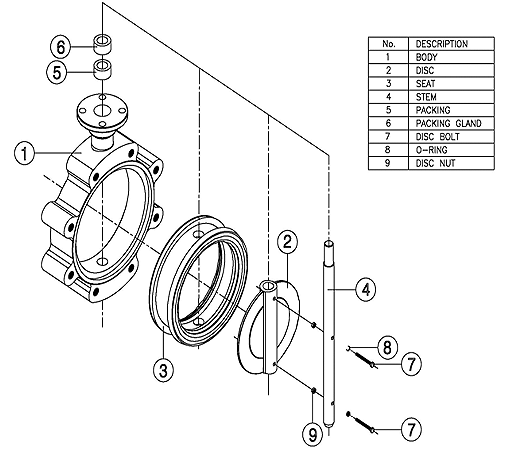
Its principal part consists of body, disc, seat and shaft, and materials of each part are selected according to the duty and working condition |
|
 |
|
 |
|
 |
|
(1) Pre-Inspection
- Before installation of valve to the Pipe Line, It is highly recommended to inspect a valve closely as below
a. Inspecting Valve & Accessory
- Ensure any damage that might be occurred during the transportation.
- Remove th protection cover of valve just before installation and clean a dust or mote with an air blaster of smooth dust cloth/mop.
- Check the tightness of all kinds of bolts and nuts
b. Inspecting Pipeline
- Remove foreign materials such as a rust, welding chip, etc, which remain in the pipe of flange.
- Make sure the clearness of pipe flange and gasket surface.
※ Note : When the fluid is flowing through the line, any foreign materail is subject to scratch the disc, seat and inner body, so that the scratch may cause leakage and shortening of the valve lifetime.
(2) Intallation
a. Make sure the pipeline and pipe flange faces are clean. any foreign material such as pipe scale,metal chips, welding slag, welding rods, etc. can obstruct disc movement or damage the disc or seat.
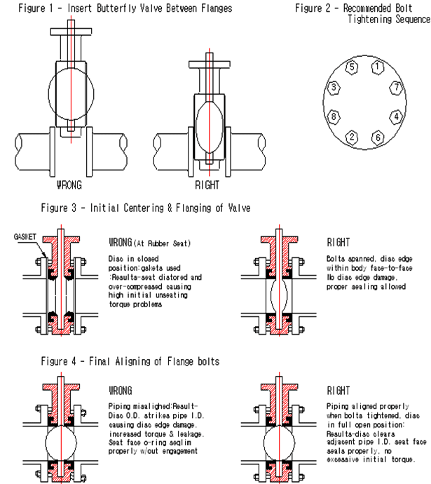
b. The elastomer seat had moulded o-ring on the face of the seat. as a result, no gaskets are required as these o-ring serve the function of a gasket. permit the valve body to be easily dropped between the flanges without contacting the pipe flanges.
c. Align the piping and then spread the pipe flanges a distance apart so as to permit the valve body to be easily dropped between the flanges without contacting the pipe flanges.
d. Check to see that the valve disc had been positioned to a partially open position with the disc edge about 10mm from the face of the seat
(approximately 10。 open).
e. Insert the valve between the flanges, taking care not to damage the seat face.
Always pick up by the locating holesor by using a nylon sling on the neck of the body.
Never pick up the valve by the actuator or operator mounted on top of the valve.
f. Place the valve between flanges, centre it, and then span the valve body with all flange bolts, but do not tighten the bolts. Carefully open the disc to the full open position, making sure the disc does not hit the adjacent pipe I.D. Now systematically remove jack bolts or other flange spreaders, and hand-tighten the flange bolts. Very slowly close the valve disc to ensure disc edge clearance from the adjacent pipe flange I.D. Now open and tighten all flange bolts per specification. finally repeat a full open rotation of the disc to ensure proper clearances.
※ Note : Please refer to the Figure 1 & 2 for Installation
|
|
 |
|
(1) Operation Notice
Before operating check The parts of valve was already regulated by manufacturer, but operate valve after rechecking as follows.
a. Check the leakage of packing and seat part in condition of full closure.
b. Check the deposit ( the other substance such as concrete ) in valve.
c. Check that valve have the proper torque by hand-wheel.
d. Check the leakage and provisional oil supply on the speed reducing device.
e. Check sufficient grease put into the necessary parts.
(2) Operation check
a. If the valve fond leakage because of deposits by the fluid flowing, such as sand, dust and the others. This shall be cleaned.
b. Check leakage by scraching the seat, Exchange seat if the seat leakage found during checking the valve by opening the disc and then closing cannot be repaired.
|
| |
 |
|
Check maintenance of valve considered valve operating condition and life
(1) Oil supply for each part
a. Greese supply for reducing device.
b. Oil supply for the electric control device
Each reducing device shall be supplied by grease pouring.
Grease by putting device is poured into the grease nipple on the worm gear box.
Putting times are different using frequency, but in general, put 1 or 2 times per year.
(2) Check for a long period for stop
For period of stop, check oil supply and condition.
(3) Inpection / Minor Treatment
a. Packing
Most leakage from packing part of valve could be prevented effectively by tightening of packing or packing gland. If the leaks don't stop continuously, packing replacement shall be required.
b. Seat
If it sounds the leakage from inside of the valve after full closing od disc, or If the fluid flows over the drain valve, which is equipped at the bottom of pipe, then check the seat condition and necessity of the replacement. |
| |
 |
|
(1) Packing Replacement :
a. Remove the operator with any accessories(Lever or Gear)
b. Take out the pcking gland
c. Remove the stem packing by using a pcking extractor suchas the corkscrew, awl and gimlet
and then replace new one.
(2) Seat Replacement
a. Open the disc of valve(5~10degree)
b. Remove the operator , packing gland and packing, and remove disc bolt.
c. Pull out the stem and Take out the Rubber seat
d. Replace the new seat by using a kind of Rubber or urethane hammer.
e. Once disassemble the packing and stem of the valve for replacement of the seat,
please use new packing kits when assemble the part after replacing the seat. |
 |
|
| This manual describes "Installation, Operation and Maintenance of DK-H Series butterfly valve. |
 |
|
|
 |
|
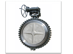
DK-H sereies is the particular term of DK TMI to distinguish from other types of valves and is nomally called as Double eccentric or High Performance Butterfly Valve in the valve industry.
DK-H Series has been designed and developed to be able to do as good working under high temperature and pressure, high vacuum condition.
This series has been applied the 0(zero) eakage, double eccentriccity construction. Furthermore, this series can be applied onvarious seat type, such as PTFE, RTFE, PEEK, and PCTFE as well as NBR, EPDM, and Viton seated Cargo valve Application. |
|
 |
DK H-Series is generally classified by open/closed method as follows.
(1) By Operator(Only in Manual)
- Lever Type
This valve type can be opened or closed by operator personally Mainly, applied on small size, up to 6"(200A)
- Hand wheel operating type
This valve has the reduction gear box with hand wheel on the top of valve.
the operation shall be made as indicator by operator.
(2) By Appearance
DK-H series is Classified as Wafer type, Lug Type and Flange type acc. To it's appearance.
Its principal part consists of body, disc, seat and shaft, and materials of each part are selected according to the duty and working condition |
|
 |
|
 |
|
 |
|
(1) Pre-Inspection
- Before installation of valve to the Pipe Line, It is highly recommended to inspect a valve closely as below
a. Inspecting Valve & Accessory
- Ensure any damage that might be occurred during the transportation.
- Remove th protection cover of valve just before installation and clean a dust or mote with an air blaster of smooth dust cloth/mop.
- Check the tightness of all kinds of bolts and nuts
b. Inspecting Pipeline
- Remove foreign materials such as a rust, welding chip, etc, which remain in the pipe of flange.
- Make sure the clearness of pipe flange and gasket surface.
※ Note : When the fluid is flowing through the line, any foreign materail is subject to scratch the disc, seat and inner body, so that the scratch may cause leakage and shortening of the valve lifetime.
(2) Intallation
a. Make sure the pipeline and pipe flange faces are clean. any foreign material such as pipe scale, metal chips, welding slag, welding rods, etc. can obstruct disc movement or damage the disc or seat.
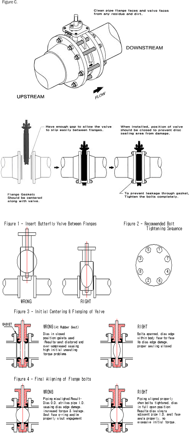
b. The Valve is designed to seal against Bi-diectional flow and can therefore be installed with in either direction. However, please mount valves in the flow direction arrow. (Figure C) enhanced sealing life will be obtained with upstream flow against the shaft side of the disc.
This preferred flow direction is shown on the name plate or marked on valve body adjacent to the operator and also on the General Assembly Drawing.
The valve may be installed in the pipeline with the valve shaft in a horizontal,vertical or Intermediate position.
c. Ensure that the valve is closed prior to installation to avoid the risk or damage to the sealing surfaces.
d. The Valve must be lifted by the eyebolt or lifting eyes provided with the valve
e. The Valve must not be lifted by the operator or handwheel.
f. The Valve need gaskets between left side and Right side of pipeline flange
g. Insert the valve between the flanges, taking care not to damage the seat face.
h. Place the valve between flanges, centre it, and then span the valve body with all flange bolts, but do not tighten the bolts. Carefully open the disc to the full open position, making sure the disc does not hit the adjacent pipe I.D. systematically remove jack bolts or bolts per specification. finally repeat a full open rotation of the disc to ensure proper clearances other flange spreaders, and hand-tighten the flange bolts. Very slowly close the valve disc to ensure disc edge clearance from the adjacent pipe flange I.D. Now open and tighten all flange bolts per specification. Finally repeat a full open rotation of the disc to ensure proper clearances.
i. he Lugged or Double Flanged type valve is suitable for dead and Service,.ie end of line duty in either direction(In case of the valve specified for both direction) to the full rating pressure of the piping system.
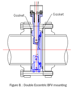
j. See the figures B. for the installation.
k. Please refer to Figure 1 & 2 for more informations
|
|
 |
|
(1) Operation Notice
Before operating check The parts of valve was already regulated by manufacturer, but operate valve after rechecking as follows.
a. Check the leakage of packing and seat part in condition of full closure.
b. Check the deposit ( the other substance such as concrete ) in valve
c. Check that valve have the proper torque by hand-wheel.
d. Check the leakage and provisional oil supply on the speed reducing device.
e. Check sufficient grease put into the necessary parts.
(2) Operation check
a. If the valve fond leakage because of deposits by the fluid flowing, such as sand, dust and the others. This shall be cleaned.
b. Check leakage by scraching the seat, Exchange seat if the seat leakage found during checking the valve by opening the disc and then closing cannot be repaired. |
| |
 |
|
High seal valve as Double eccentric(DK-H Series) does not need a particular maintenance unless any leaksare found, however, some routine inspection are recommended for safety and longer lasting life time.
(1) General maintenance
a. Visual Inspection of the body, disc and packing part of valve at the initial service or at the re-operation after long-term recess.
b. Check up the valve when abnormal sound is perceived during the operation.
c. Ensure tightness of each bolt regularly.
(2) Oil supply for each part
a. Greese supply for reducing device.
b. Oil supply for the electric control device Each reducing device shall be supplied by grease pouring.
Grease by putting device is poured into the grease nipple on the worm gear box. Putting times are different using frequency, but in general, put 1 or 2 times per year.
(3) Inpection / Minor Treatment
a. Packing
Most leakage from packing part of valve could be prevented effectively by tightening of packing or packing gland. If the leaks don't stop continuously, packing replacement shall be required.
b. Seat
If it sounds the leakage from inside of the valve after full closing od disc, or If the fluid flows over the drain valve, which is equipped at the bottom of pipe, then check the seat condition and necessity of the replacement. |
| |
 |
|
(1) Valve separation from the pipe
To repair leaking valve, the valve must be removed from pipeline and then parts must be separated as below
a. Shout down the line, and make sure no pressure inside.
b. Drain all mediums from the pipe.
c. Completely close the disc of the valve.
d. Remove the parts and remove the valve from the pipe.
e. Mark the location of each part of valve and pipe in order to be installed at same places where they were.
(2) Disassembly of the seat & Retainer
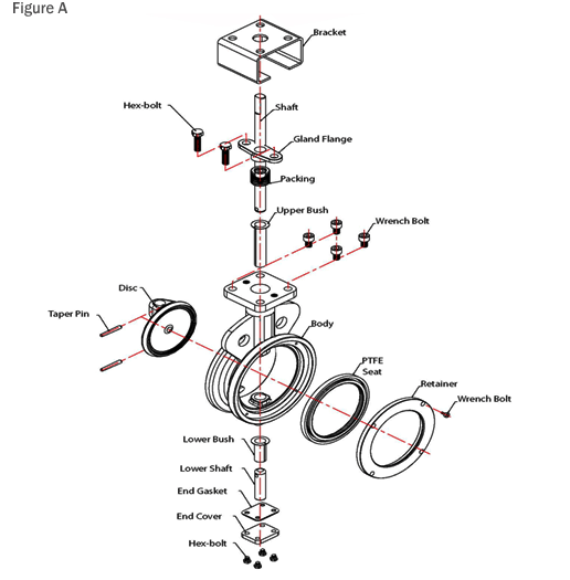
a. Open the disc of valve(5~10 degree) using a kind of rubber or urethane hammer. b. Remove a tightened "Wrench bolt" on the Retainer of the body(Please see the Figure A)
c. Remove the Retainer by lifing it up using " Wrench bolt tap"
d. Take out the seat. At this time , be careful about scratching, chopping and damage of a seat ,and clean dust or mote on the seat asssembly parts with an air blaster or smooth mop.
※ Note : After disassembly, please check the surface of the disc. If any damage of the disc is found the disc and shaft must be replaced together. In this case, Please be sure to get advice from DK TMI's staff in charge. |
(3) Packing Replacement
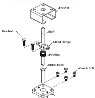
a. Remove the Bracket and Gland Flange and packing Washer after loosening a Wrench bolt as the figure below.
In case of the model without Bracket , just remove Gland flange and packing washer.
b. Remove the packing stuffs using a packing extractor such as corkscrew, awl and gimlet.
c. When you remove the packing with the tools(packing extractor), pelase be careful not to scratch and damage the wall of "Packing housing and the valve "Shaft" because the damage may cause a leakage.
d. By pushing a Packing washer or Gland flange, insert a set of packing carefully after cleaning "Packing housing"
e. After inserting the packing, assemble the Packing washer and Gland flange.
f. Hex bolt of Gland flange should be tightened enough to push a packing gland downward, but over tightness might cause over torque to valve. |
 |
|
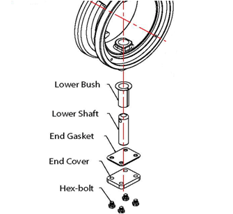
(4) End Gasket Replacement
a. Remove Hex-bolt
b. After removing the Gasket, Clean the End cover, and then replace new Gasket c. Tighten Hex bolt again.
d. At this time, over tightening on the bolt might cause damage of screw thread parts.
(5) Seat replacement
If the fluid can't be shut-off at full close position of disc, then seat-damage is suspected.
In case of seat -damage, replacement works should be followed as below
a. Please refer to Figure A for removing of Seat and Retainer
b. Please replace the damaged seat with a new one from DK TMI
c. New seat shoud be seated in state of Disc-Opening by 5~10。
d. For assembling of the Retainer ring, Please take the reverse steps of the previous disassembly.
e. Slightly tighten the bolt of the Retainer at close position and rotate the disc a couple of times.
f. Rotate the disc a couple of times and then tighten the bolt completely in state of disc opening by 5~10。
g. As a final step, rotate the disc several times to get the seat placed on right position.
This would help a seat get the most suitable contact with the disc.
h. Install the valve on the pipe line with disc fully closed.
※ Note : Over tightening of bolts may cause a damage of screw thread of bolt and tap of body. |
 |
|
|
|
|
|
